Technical Specifications
Specifications of 'SONA' Products
| Charactristics | IS 2556-1-1994 | SONA' Test Value |
| Surface Blemish | Should conform to Norms | In conformity with the Norms |
| Water Absorption % | 0.5 Max. Mean Value | 0.1 Max. Mean Value |
| Modulus of rupture (M.O.R.) | 60 Mpa Min. Mean Value | 70 Mpa Min. Mean Value |
| Crazing Resistance 0.34- 0.37 Mpa | 10 Hrs. Min. | 20 Hrs. Min. |
| Chemical Resistance | Should Conform to Norms | In Conformity with the Norms |
| Staining & Burning Resistance | Should Conform to Norms | In Conformity with the Norms |
INSTALLATION & MAINTENANCE TIPS
- Install Wash Basins with or without pedestals on CI Bracket with Rag Bolts. If wash basin is Large in size install on pedestal screwed to the floor.
- Install wall mounting E.W.C. With the help of CI chair.
- Install Floor Mounting E.W.C. Screwed to the floor.
- Avoid using Cement at the hollow bottom portion of E.W.C.
- Regular Cleaning with dry cloth / Mild Detergent is recommended to avoid stains & if required diluted Hydrochloric acid may be Used.
- Do not use hard bristled brush for cleaning so as to avoid scratches.
Your Trouble-Shooting Guide
(FOR GOLD - TYPE FITTINGS)
At Ceramics Division, SONA Ceramics, it has been our endeavour not only to provide you with the best possible service, but also to help you serve your customers better. We have been analysing the complaints received by us and have discovered that most of the complaints fall into a pattern. We would like to share the qualitative results of the analysis with you, so that you can be better prepared to handle any complaints received from your customers.
For each problem faced, the probable causes are explained. Alongside, you can find the corrective actions required to solve these problems. We hope that you would find this trouble-shooting chart useful. You could apply this for suites as well as wallvit pans
Flushing Test
1 Toilet Paper Test
The water closet shall be filled with water to its normal water seal level and charged with six pieces of usual toilet paper or polythene sheet of 0.05 mm thickness approximately 150 mm x 115 mm in size and loosely crumpled. It shall then be flushed. This test shall be repeated four times and the pan shall discharge the full charge of the paper at last three out of four times.
2 Smudge Test
The whole of the interior surface of water closet to 40 mm below the flushing rim shall be smudged with quartz powder of contrasting colour passing through 1.18 mm IS sieve and shall then be flushed observing carefully the surface of the water closet during the flushing. Immediately after the flushing, there shall be no smudge left on the bowl.
3 Holding Capacity Test
The water closet when sealed at the outlet and vent (if fitted) with water-tight seal shall be capable of holding not less than 10 1 of water between the normal water level and the highest possible water level of the water closet as installed.
4 Ball Test
Single Ball Test :The ball shall be made of non-absorbent material. The relative density of the ball shall be between 1.075 and 1.080. The diameter of the ball shall be 43 ± 0.5 mm. Place the ball into the water closet to be tested and then flush the water closet. The ball shall be discharged in the normal manner.
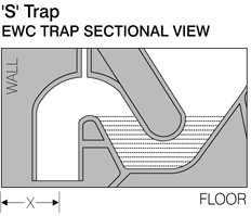 The outlet (trap) of the water
closet goes into the floor.
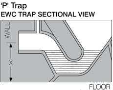 The outlet (trap) of the water
closet goes into the wall.
|
5 Fifty Ball Test
Fifty balls of non-absorbent material, having a mass each of 3.7 ± 0.1 g, and a diameter of 20 ± 0.1 mm
shall be dropped into the water closet bowl and flushed. Repeat the test five times. A minimum of 85 percent of all balls should be flushed out in the five tests. 6 Load Bearing Test
force of 4 + ° .05 kN shall be applied for period of one hour by placing it on a wooden beam with a cross
section of 100 mm x 100 mm positioned across the centre of the opening of the top surface of the WC. There shall be no damage or defect which shall occur to the WC. 7 Saw Dust Test
Specification of the Saw Dust 20 g of dry saw dust test sifted through 2 mm sieve.
Procedure: Set up the WC, cistern or flush valve and flush pipe (if required) as specified by the manufacturer. Charge the WC with water to its designed water seal level. Fully wet the entire internal surface of the WC below the rim. Sprinkle 20 g of fine dry saw dust of above specification on the inside of the WC between the normal water level and the flushing rim as completely and evenly as possible. Then flush the WC. The sprinkle saw dust should be cleaned below 40 mm of rim of WC. 8 Splash Test
Procedure: Set up the WC, cistern or flush valve and flush pipe (if required) as specified by the
manufacturer. Charge the WC with coloured water to its design water seal level. Ensure that the floor area is cleaned and dry where the splash test to be carried out. Activate the flush valve or cistern to the discharge the WC. Observe and record whether flushing water splashed over rim onto the floor. Repeat the test 5 times. Record whether the flushing water splash over the rim onto the floor. Isolated droplets up to 10 Nos., shall not be the cause for rejection. |
| Problem faced | Probable Reasons | Corrective Action |
| Tank is shaking |
Expansion plug may not be correctly fixed in the tank's fixing hole provided towards the back of the closet. |
Fix the expansion plug provided. |
| Tank holding screw may not be tightened fully. |
Tighten the tank holding screw evenly till it cannot be tightened any further with one hand. |
|
| Continuous leakage of water from the cistern |
Arm may be fixed in a wrong direction. |
Fix the arm such that the shorter arm side is facing the front of the cistern. |
| Valve ring may not be fixed properly to the bottom of the body. |
Fix the valve ring to the top of the groove provided in the body. Ensure that the valve ring sits securely around the groove. |
|
| Valve ring may have cracked or could be worn out. |
Replace the valve ring. | |
| Lifting rod and floating body assembly may not be perpendicular. |
Adjust the bracket so that its center hole aligns with the hole provided in the lid of the cistern. |
|
| Lifting rod and floating body assembly may not be guided through the guide hole provided in the bottom of the valve seat. |
Guide the lifting rod through the hole provided in the bottom of the valve seat. |
|
| Cistern not fully tightened to the closet. | Tighten tank holding screws evenly till they cannot be tightened further with one hand. |
|
| Discharge of water stops abruptly when the flush knob is pulled and released |
Water may be overflowing through the floating body. |
Turn the adjusting screw provided on the top of the inlet in the anti clockwise direction. Reduce the water level such that the water level shuts off below the 'over-flow' level. |
| Buoyancy may not be created for the floating body. |
1. Push stop dog (black rubber tube) which is fixed to the lifting rod such that top end of the stop dog touches the bottom of the lifting bar. |
|
| 2. Adjust the lifting bar such that the hole provided near the top-end threaded portion of the lifting-bar is just visible over the lid screw (when observed in assembled condition). |
||
| Water does not enter the cistern through the inlet |
The inlet may be in the fully closed position. |
Turn the adjusting screw provided on the top of the inlet in the clockwise direction to open the inlet. |
| Water line may be choked. | Ensure periodical cleaning of water tank and water lines. |
|
| Water quantity insufficient for effective flushing |
Float ball height adjusted to lower quantity of water discharge. |
Turn the adjusting screw provided on the top of the inlet in clock wise direction to increase the discharge level. (Caution: The water level may be increased till the water from the inlet shuts off at the 'top-line' mark provided on the floating body). |
| Water leakage observed between cistern and closet during flushing. |
Water divider may not be properly fixed. |
Fix the water divider such that the 2 weep holes provided in it face each other after installation. Ensure that the inlet of the water divider is passing through the outlet of\ the valve-seat fully |
Continuous innovation and improvement in manufacturing techniques and products are carried out regularly. We reserve the right to supply articles which may not correspond exactly with the particulars given in this booklet.
Installation & Instructions
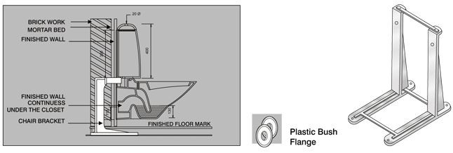
Wall hung
|
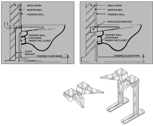
1. A cast-iron chair bracket grouted into the wall and the
floor is recommended for use while installing SONA
Wallvit Pan.
2. Cantilever brackets with provision of 4'' of the brackets
into the wall can also be used.
3. The cantilever brackets used should have the distance
between the center of the back and front slots as 95 mm.
4. Ensure that while grouting the cantilever brackets into
the wall, they are fixed in exactly the same plane. A
distance between centers of the slots of one bracket to
the other brackets should be exactly as per diagram.
5. For either type of fixing, please ensure that a rubber
gasket is fitted between the bracket and the closet to
provide adequate cushioning and protection from direct
contact between the ceramic closet and metal brackets.
|
 |
Wall Mount Couple suite
Under Counter
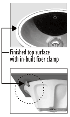 |
|
|||||||
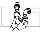 |
Make the final drain and faucet connections to complete the basin installation. Be sure to follow all instructions packed with the drain and faucet. Clean up with a non-abrasive cleaner. |
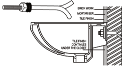
Wall Hung BasinFixing : The rag bolt should be first grouted into the wall using cement / concrete, (as shown)
as per distance between slots provided in the wash basin. The bolts should be fixed perpendicular to the wall. Allow cement / concrete to set. Check if the Rag bolts are firmly fixed. Fix the Wash Basin in the bolt using Nut & Washer. |
 |
Counter Wash Basin
(A) BEFORE YOU BEGIN
1. Due to the typical nature of the installation, under counter basin should be installed by trained and experienced installers.
2. Inspect the waste and supply tubing if necessary.
3 Install the basin in such a way, that it's removal in future can be done freely and without damage.
4. Prior to installation, open the new basin and inspect it for damage. Return the product to its protective packing untill it is ready to be installed.
5. Observe all local plumbing and building codes.
(B) TOOLS AND MATERIALS
Sealant, Pencil, Tape measure, Sharp knife of scissors, Keyhole or saber saw, Drill (1/2 dia, drill bit or larger) glasses, Hammer, Rags or paper toweling
NOTE : you may require different, more specialised tools to install this basin of counter top materials other than wood or wood composites.
|
(C) INSTALL THE BASIN
NOTE : Install the basin in such a way, that it's removal in future can be done freely and without damage.
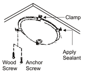
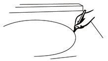
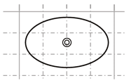
1. Check the desired lavatory location for clearance between the back splash, faucet, fixture and cabinet. 2. Cut out the template. 3. Carefully position and trace the template on the counter top. 4. Mark the faucet hole centerline on the counter top. 5. Drill a 1/2" pilot hole on the inside of the cut line. 6. Cut out the counter top opening with a saber or keyhole saw. |
 |
For Wood Counter tops1. Mark and per-drill the wood screw
holes at the locations. 2. Waterproof any exposed areas of wood. |
 |
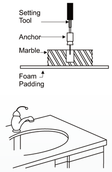
For Marble Counter tops1. Position the counter top upside down on foam padding to protect the surface. Mark
and drill 3/16" holes 5/8" deep at the locations shown on the template. 2. Use a setting tool and hammer to secure the anchors. For All Installations1. If the counter top has not been installed, install it at this time.
2. Drill the faucet holes according to the faucet installation instructions. 3. Install the faucet to the counter top according to the manufacture's instructions. 4. Install the drain to the lavatory according to the manufacture's instructions. |
 |
